

 Technical Information Power And Control Cables Power Appendixes Guide to the Wiring Regulations Inspection, Testing and Certifcation ; Continuity testing
 صفحه Inspection, Testing and Certifcation ; Continuity testing
| Inspection, Testing and Certifcation ; Continuity testing | ||
|
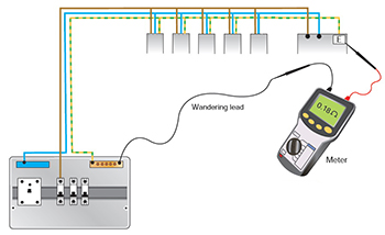
This is the frst suggested test as it is important for the safety of the circuit, and it helps confrm a reference for the remainder of the tests. Continuity testing is carried out on all protective conductors including cpcs, main and supplementary protective bonding conductors. The test is carried out with a low d.c. voltage continuity tester, and this may detect loose and unsound connections; other instruments may be used.This brings us to the two popular methods for continuity testing, namely: 1- Wandering lead method; 2- Utilization of circuit cable by ‘shorting’ R1+R2 method . |
||
 |
 |
|
|
Wandering lead method You will notice by studying the fgure that the cpc has not been removed from the earth terminal at the distribution board. This is due to the fact that there are parallel metallic earth return paths and removal of this conductor will not change this. |
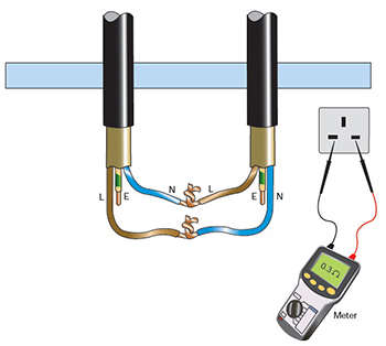
Utilizing the circuit cable and R1 + R2 method The method is simple enough, and if the line conductor is used, this method can be used to record the circuit’s Rl + R2 value . The method does fnd favour with some, and can be used to establish a circuit’s earth fault loop impedance. |
|
|
Ring continuity The continuity of ring fnal circuits is something that is a little more involved. Methods have evolved over the years to establish whether the rings are indeed wired as ring circuits, and not ‘shorted’ forming a ‘fgure of eight’ layout and similar. |
||
 |
 |
 |
|
Stage 1 - open loop resistances : Measure the end-to-end resistance of each conductor, Rl (line), Rn (neutral) and R2 (cpc) respectively . An open circuit result would suggest either the incorrect conductors have been selected or the circuit is incorrectly terminated. As phase and neutral conductors will be of the same cross-sectional area, the resistance values obtained for both conductors should be similar |
Stage 2 - interconnected L-N : With phase and neutral interconnected, measure resistance between phase and neutral conductors at each socket outlet using a continuity tester or similar instrument. If the ring is not interconnected the measurements taken on the ring circuit will be similar. The measurements obtained will be approximately one quarter of the resistance of the sum of the open loop resistances from stage 1, that is (Rj + Rn)/4. |
Stage 3 - interconnected L-cpc (for all insulated systems) : With phase and cpc interconnected, measure resistance between phase and cpc conductors at each socket outlet using a continuity tester or similar instrument. If the ring is not interconnected the measurements taken on the ring circuit will be similar. The measurements obtained will be approximately one quarter of the resistance of the sum of the open loop resistances from stage 1,that is (R1 + R2)/4. |